Multicast Transmission of Scalable Video using Receiver-driven Hierarchical
FEC
Wai-tian Tan and Avideh Zakhor
Department of Electrical Engineering and Computer Sciences
University of California, Berkeley, CA 94720, USA
email: {dtan avz}@eecs.berkeley.edu
1. Introduction
The deployment of IP multicast in the MBONE has provided
a convenient and efficient way of disseminating video information to multiple
recipients over the Internet. However, since the recipients may have different
delay tolerances and are typically connected to the source via paths of
different delay, bandwidth and loss characteristics, traditional approaches
to flow and error controls based on source adaptations may not be effective.
A more elegant alternative is the receiver-driven approach [1]
which allows receivers to decide on the communication parameters. For instance,
an effective solution to the bandwidth heterogeneity of today's high-speed
networks is to use scalable video compression [2,18,19,20,22]
with layered multicast [1]. Under layered multicast,
scalable video is partitioned into different layers which are carried using
different multicast groups. Each receiver can then individually subscribe
or unsubscribe to those multicast groups to effect flow control. Other
schemes have also been proposed that require additional support from the
network, such as explicit congestion notification and hop-by-hop flow control,
to further enhance the overall bandwidth utilization by dynamically adjusting
the number of video layers and the rate of each layer in a layered multicast
setting [3].
On the error control side, most work has focused on providing
end-to-end reliability based on retransmissions [4,
5, 6] or hybrid schemes employing
forward error correction (FEC) and retransmissions [7,8].
Because the cost of retransmissions in a multicast setting is high, such
schemes are often justified only for low bandwidth applications that require
reliability, such as the shared white-board in the MBONE tools. Retransmissions
may also be inapplicable for real-time applications, especially when round
trip time is long. In contrast, pure FEC based schemes are simpler, but
can be wasteful as redundancy packets are transmitted to all receivers
regardless of whether they are needed or not.
In this work, we will investigate the application of hierarchical
FEC as an error control method for scalable video multicasting. By hierarchical
FEC, we mean the production of embedded FEC or redundancy streams, each
of which belongs to a different multicast group. In such a way, subscribing
to more groups corresponds to higher level of protection. There are two
advantages to using hierarchical FEC. First, each receiver can independently
adjust the desired level of protection based on past reception statistics
and the application's delay tolerance. This receiver-driven approach to
FEC is more flexible than most existing FEC schemes for multicast where
the source determines a set of redundancy packets which are then multicast
to every recipient [8]. Second, each receiver will
subscribe to only as many redundancy layers as necessary, reducing overall
bandwidth utilization. Thus, the hierarchical nature of the FEC layers
ensures minimum network utilization through sharing of common streams.
An effective means to combat burstiness in packet losses is suggested in
[9] where redundancy packets are transmitted at
a later time than the actual data packets. Following [9],
we delay the transmission of FEC layers to relieve the effects of bursty
losses. The additional latency associated with the FEC layers creates a
trade-off between higher levels of protection and increased latency, and
also as a disincentive for receivers to unnecessarily use FEC.
The use of scalable video has three implications. First,
it is possible to achieve flow control by adjusting the number of data
layers based on the observed channel characteristics. Second, it is possible
to drop data layers to make room for FEC layers so as not to increase overall
transmission rate. Third, it is possible to strategically provide FEC only
to the most important data layer so as to reduce the amount of FEC traffic.
The optimal division of the available bandwidth between data and FEC depends
on the error resilience of the scalable video source. Since less error-resilient
compression schemes suffer higher penalty when packets are lost, they tend
to allocate larger portions of the available bandwidth for FEC. This generally
causes the quality of the received video to be lower. As
a result, it is desirable to have error resilience even when FEC is used
for error control. In this paper, we will evaluate our framework using
a scalable and error resilient compression scheme that we have developed
for Internet transmissions [18,19,20].
The remaining of the paper is organised as follows. An
overview of our proposed system architecture is described in Section
2. The selection of error control code for implementing the hierarchical
FEC is described in Section 3. We will describe
our scalable video compression scheme and its application to the proposed
hierarchical FEC framework in Section 4 and
present experimental results in Section 5.
Conclusion and future work are in Section 6.
2. Proposed System Architecture
In a multicast environment, besides bandwidth heterogeneity,
different users may experience different packet loss characteristics and
may have different degrees of tolerance to latency. For example, in live
multicast of a lecture, participants who want to ask questions and interact
with the lecturer desire stringent real-time constraints on the video while
passive listeners may be willing to sacrifice latency for higher video
quality. Because of the high bandwidth required for video traffic, generating
a separate stream for every possible set of user requirements and channel
loss rate is infeasible. Instead, we wish to cater to different users with
varying latency requirements by providing a framework in which each user
can individually trade-off latency for quality.
2.1 Video Sources
In our proposed scheme, a scalable video source not only
sends video packets to multiple multicast groups as in layered multicast,
it also constructs hierarchical FEC layers for the video layers.
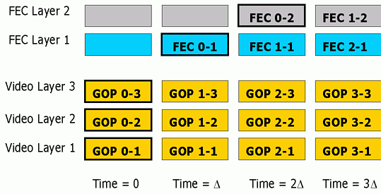
Fig.1 illustrates our proposed
scheme using 3 layers of video and 2 layers of hierarchical FEC:
Fig.1: Timing Diagram of Hierarchical FEC Scheme
where GOP-x-y denotes the y-th data layer corresponding
to the x-th GOP. Similarly, FEC-x-y denotes the y-th FEC layer generated
for the x-th GOP.
Addresses D1, D2,
D3 are used to carry layered video data and addresses
R1, R2 are used to carry redundancy
packets. All layers of video data corresponding to the same group of pictures
(GOP) that are compressed together are transmitted in the same time slot.
As a result, users with stringent delay requirements can simply subscribe
to D1, and possibly D2 and D3
depending on the bandwidth that is available to them. Users with higher
tolerance of latency who are also experiencing packet losses can subscribe
to addresses R1 and potentially R2
to obtain redundancy to repair lost packets at the cost of extra delay.
The reason for spreading the redundancy layers for the same GOP across
different time slots is to achieve interleaving, which is an effective
means of combating bursty losses often experienced in the Internet [9].
Fig. 2 summarizes the behavior for different
users. We see that FEC packets are only transmitted to branches that lead
to subscribers requiring FEC, thereby reducing overall network load.
In order to determine the optimum distribution of FEC
packets across video layers, one can setup and solve an optimization problem
[18]. Instead, in the experiments reported
in this paper, we only apply FEC to the first layer of Video rather than
all layers. The approach is motivated by the fact
that (1) the first layer video is generally much more important than other
layers, and (2) it reduces the computation each receiver needs to decide
the number of FEC layers to subscribe to. The packets in the FEC
layers are generated by applying the FEC code described in Section
3 on the packet level. The sizes of the FEC layers determine
the granularity of available protection. Generally, providing many
small FEC layers improves the granularity of available protection levels
but incurs a higher networking overhead associated with maintaining the
larger number of multicast groups.
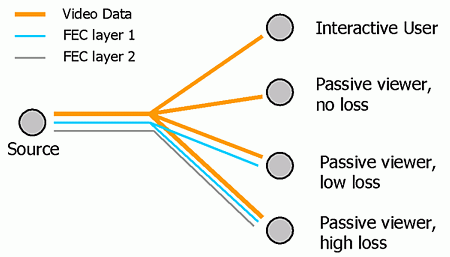
Fig.2: Receiver-driven Hierarchical FEC schemes with multiple
Receivers
2.2 Video Receivers
A central problem in layered multicast is determining the
rate control algorithm at the receivers. Receiver-driven layered multicast
(RLM) of [1] is an early scheme that drops a layer
when congestion is detected and "probes" for more bandwidth when losses
are absent. Since the act of probing for bandwidth may cause congestion
which leads other receivers to mistakenly reduce their subscription levels,
the difficult tasks of coordinating probes and communicating their results
are necessary [1,12].
An alternative approach that does not involve probing, but instead calculates
the bandwidth directly using measured quantities at the receiver is described
in [10,12]. The
scheme is based on the TCP-friendly equation [11]
that estimates the average throughput T of a TCP connection under
packet loss rate p and round trip time rtt:
(1)
where MTU, the maximum transport unit, is a constant
that is often taken to be 500 bytes.
Because the problem of rate control in a layered multicast
setting is still an area of active research and that our proposed hierarchical
FEC scheme does not depend on any specific rate control scheme, we adopt
a simple rate control algorithm which is sufficient for the scale of experiments
we are performing. Specifically, our rate control scheme is similar to
[10] in that every receiver estimates the available
bandwidth according to Equation 1 in an uncoordinated fashion. To
avoid unnecessary reaction to network transients, the bandwidth calculation
is performed relatively infrequently, with a period of 50 seconds.
The packet loss rate p is measured over the whole period, and over
all data and FEC layers while rtt is updated only once every 5 seconds
to reduce the load on the source. Clearly, it is possible to augment our
rate control approach by adding synchonization mechanisms as in [12].
Given a dynamic bandwidth constraint obtained by periodically
applying Equation 1, the receiver then decides on the optimal number of
data versus FEC layers to subscribe. The partition of bandwidth between
data and FEC depends on the characteristics of the scalable video compression
method used and is described in Section 4.2.
3. Selection of Error Control Code for Hierarchical
FEC
An effective FEC scheme will allow recovery of lost data
packets with as little redundancy packets as possible. This is achieved
when the loss of any m data packets are recoverable from any m
parity packets. Such properties are often referred to as maximal distance
separable (MDS) in algebraic coding theory [14].
An example of MDS code is the Reed-Solomon code. Fig.
3 shows the use of an (n, k) MDS code which takes k data
packets and produces n-k parity packets. The basic idea behind hierarchical
FEC is to partition the n-k parity packets into FEC layers of potentially
different sizes. A source may decide to transmit the data packets with
any number of FEC layers, and a receiver will be able to recover all the
data packets from any combinations of k data or parity packets.
For example, if we form the first FEC layer by taking the first f1
packets from the n-k parity packets, since any m lost data
packets can be corrected using any m of the n-k parity packets,
they can also be corrected by any m packets in the first FEC layer
as long as m does not exceed f1. Similarly, the
second FEC layer is formed by the next f2 parity packets
and any combination of m parity packets from the first two FEC layers
can correct any m lost data packets as long as m does not
exceed f1+f2.
Fig. 3: Generation of FEC layers by puncturing MDS codes
The successive refinement property of Reed-Solomon codes
has long been exploited in data communications to provide incremental redundancy.
For example, in the scheme of [15], a sender will
continually transmit parity packets until a receiver has enough parity
packet to recover all lost data packets. More recently, the dual code of
Reed-Solomon code, which is also MDS, has been used to reduce the average
transmission time of data in a large reliable data multicast setting [16].
Following [16], we select the
dual code of the Reed-Solomon code as the MDS code for generating FEC packets.
The dual code has no theoretical advantage over Reed-Solomon code and is
chosen primarily because of the availability of existing software implementations
[17].
4. Selection of Scalable Video Compression
In this section, we will describe our error resilient scalable
video codec [18,20] for
actual experiments on the MBONE. The codec is chosen because
-
it is specifically designed to limit error propagation due
to packet losses
-
it admits real-time software-only encoding and decoding [19]
-
it is finely scalable
-
it has comparable compression performance compared to non-scalable
compression schemes such as MPEG-1
The ability to limit the effects of packet loss is important
since even with our
proposed architecture in Section
2, packet losses may still be present due to traffic burstiness or
because real-time constraints have precluded the use of FEC layers. Furthermore,
a more error-resilient scheme requires less FEC at the same loss rate.
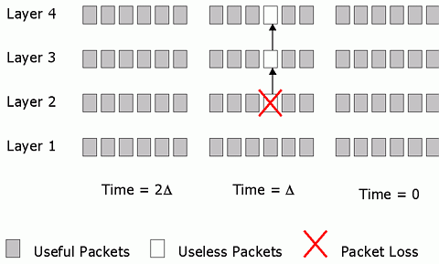
Under our proposed video compression scheme, when a packet is lost, errors
do not propagate to other packets in the same layer and only propagate
to one packet in the upper layer. As is shown in Fig.
4, this is in contrast to most scalable video compression schemes which
assume transport prioritization and produce packets that are highly dependent.
Fig.4: Data Dependency of Proposed Scalable Video
4.1 Achieving Rate Scalability and Resilience
The proposed compression scheme is based on 3-D subband coding
followed by hierarchical block coding [19]. After
subband analysis, we perform data partitioning as follows. Each of the
M subbands is divided into an equal number of coefficient blocks,
say P. We then form P components from the coefficient blocks
by allocating one coefficient block from each subband to each component.
The coefficient blocks of a particular component are chosen in such a way
as to correspond to a different spatio-temporal region . This is
done to ensure that a loss of a component does not result in complete loss
of information about any one particular spatio-temporal region in the video.
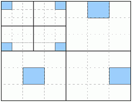
Fig. 5 illustrates the partitioning in the 2-D case where seven subbands
are obtained, each of which is divided into 9 blocks. The colored
blocks represent one possible way to form a component.
Fig. 5: Data Partitioning of Subbands
Each component is then compressed independently as follows.
Each coefficient block is split into bit-planes. Each bit-plane is compressed
using hierarchical block coding of [19] to produce
a small codeword which provides fine granularity for layered packetization.
Packetization is carried out so that the bit-plane offering the best rate-distortion
trade-off is packed first. The scheme is illustrated in Fig.
6.
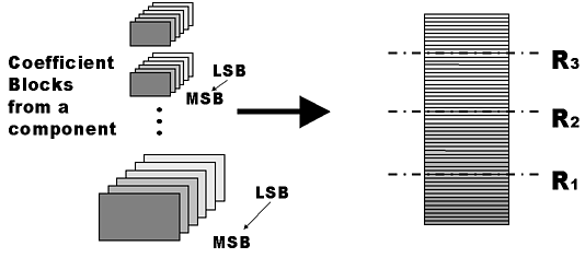
Fig. 6: Compression into scalable video with restricted data
dependence
The first layer packets are obtained by truncating the
compressed bit-planes at rate R1 and the second layer
is formed by the portion between rates R2 and R1,
etc. In such a way, the loss of a packet in any layer will only affect
packets in higher layers that correspond to the same component, as shown
in Fig. 4.
4.2 Partition of bandwidth between Data and FEC
In this section, we consider the problem of dividing the
available bandwidth between data and FEC layers. Our objective is to minimize
the expected distortion given an estimate of the packet loss rate and a
priori knowledge of the rate-distortion characteristics of the video
material.
Assume constant packet sizes. When d layers of
data are subscribed by a receiver, the expected distortion is given by:
(2)
where Di is the distortion associated with
decoding i data layers and pi is the probability
that we decode at distortion level Di,. Assuming
a total of f FEC layers are subscribed and that each data
layer and FEC layer contains Nd and Nf
packets respectively, the bandwidth constraint of B packets results
in:
(3)
The quantities Di are given by the rate-distortion
characteristics of video source and do not depend on the observed packet
loss rate p. The Di can be explicitly computed
at the source and then communicated to the receivers. Alternatively,
one can classify video sources according to their characteristics and then
generate representative values for Di for every class.
In that case, the source can be relieved from the task of having to compute
the distortions associated with every possible rate. The probabilities
pi depend on p and the data dependencies between
packets in the scalable bit-stream. For data dependencies given by
Fig. 6, the probability that a first layer packet
is lost and cannot be recovered by FEC is given by:
The other pi are given by:
Formally, the optimation problem is to find the combination
of f and d that satisfies the bandwidth constraint given
by Equation 3 and minimizes the expected distortion given by Equation 2.
Instead of testing all possible f and d that satisfy the
bandwidth constraint and search for the combination that yields minimum
expected distortion, the problem can be simplified by observing that the
expected distortion is monotonically decreasing with f and d.
As a result, it suffices to test all possible d from 1 to B/Nd
while keeping f as large as possible without exceeding the bandwidth
constraint. Each receiver then performs the minimization by performing
a linear search of d from 1 to B/Nd . The
optimal number of data layers is then computed as:
The optimality is only within the specified framework.
First, a more general approach of providing FEC to all layers of data instead
of only the first layer can yield lower distortion given the same total
bandwidth for data and FEC layers, but increases the complexity of the
receivers. When only the first layer is protected, the bandwidth partitioning
problem is analogous to partitioning B packets to 2 bins, one for
data and one for first layer FEC. This involves only an one dimensional
search. When N data layers are protected by FEC, we have to
consider all possible partitioning of B packets into N bins,
one for data and one for FEC for each of the protected data layers. This
involves an N dimensional search in which the dependency between layers
needs to be taken into account. Second, the granularity of the available
levels of protection is dictated by the sizes of the FEC layers. Since
a receiver cannot subscribe to a fraction of a layer, the optimization
is only within all possible levels of protection provided.
4.3 Compression Performance and Speed
The compression performance of the proposed codec is found
to be comparable to MPEG-1 implementation reported in [21]
at the bit rate range of 500 kbps to 3 Mbps for a talking
head sequence and a high motion sequence [18].
It also permits real-time encoding and decoding on current workstations.
Specifically, in the bit rate range of 500 kbps to 3 Mbps,
encoding and decoding both proceed at the range of 18 fps to 12
fps.
5. Experimental Results
In this section, we will describe actual MBONE experiments
using the proposed scheme. Multicast experiments are performed using UC
Berkeley as the source and two machines at Georgia Tech and ISI in Los
Angeles as receivers. The paths from Berkeley to ISI and Georgia Tech traverses
12 and 13 links respectively with average round trip times of 28 and 80
ms respectively. There is a total of 7 common links for the two
paths. The video source is the Raider sequence at 12 fps
and size 320x224. A total of 4 data layers each of 100 kbps and
4 FEC layers each of 50 kbps are generated. In Fig.
1, every GOP spans 4 video frames or 1/3 second, and consists of 14
packets of size 320 bytes per data layer, and 7 packets of size 320 bytes
per FEC layer. Therefore, an additional latency of 4/3 seconds is introduced
when a user decides to subscribes to all FEC layers.
We perform two experiments. In the first experiment, both
receivers have stringent real-time requirements so that no FEC layers will
be subscribed to. In the second experiment, which is run immediately after
the first one, receivers are non-interactive and when loss rates are non-trivial,
they may sacrifice some data layers to yield bandwidth to FEC layers.
In our experiments, the link from Berkeley to Georgia
Tech is never congested and no packet losses are observed. As a result,
the receiver at Georgia Tech is subscribing at the maximum number of 4
data layers and without any FEC layers in both experiments. The link from
Berkeley to ISI however, has an average packet loss rate of over 18% and
given a rtt of about 28 ms, Equation 1 results in an average
throughput of 400 kbps. In the first experiment, all of the 400
kbps is allocated to data whereas in the second experiment, 200
kbps is allocated to data and the other 200 kbps to FEC.
The partition of bandwidth between FEC and data is determined by the measured
packet loss rate in such a way that the expected distortion is minimized,
as described in Section 4.2. The rate-distortion
characteristics of the video is precomputed at the source and released
to the receivers before the experiment.
Fig. 7 shows the packet loss
rates experienced at the different data layers in the two experiments for
the connection from Berkeley to ISI. It is observed that the actual observed
packet loss rates do not change significantly between the two experiments
and that the packet loss rate across layers is more or less constant.
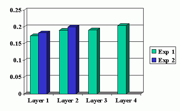
Fig. 7: Observed packet loss rate at different data layers
(Berkeley to ISI)
Fig. 8 shows the the fraction
of packets received per GOP for experiment 2 for the Berkeley to ISI connection.
We observe that when measured over intervals of 1/3 second, packet losses
show much burstiness, which necessitates the delay in sending the FEC layers.
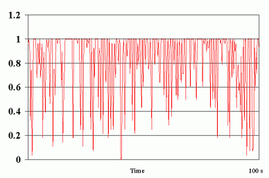
Fig. 8: Packet reception rate for experiment 2 (Berkeley
to ISI)
Each experiment is run for a duration of 300 GOP or approximately
100 seconds. For experiment 2, there are 130 GOPs out of 300 in which at
least one first layer packet is lost. Of the 130 GOPs, 116 are corrected
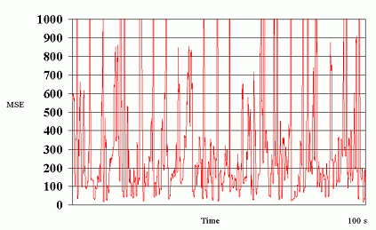
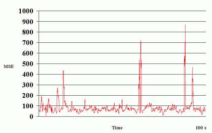
by the use of FEC. The decoded video trace for experiments 1 and 2 are
shown in Fig. 9.
Fig. 9: MSE trace for video in experiments 1 (top) and 2
(bottom) from Berkeley to ISI
The average distortion for experiments 1 and 2 are 333 and
85 respectively. Even though both experiments consume the same bandwidth,
the use of FEC for the first layer enhances the reception quality of experiment
2 at the expense of an extra 4/3 second of latency.
6. Conclusions and Future Work
We have described in this paper a scheme using scalable video
with receiver-driven hierarchical FEC so that each receiver can individually
trade-off latency for better reception quality. The scheme is efficient
in that FEC is provided only for the most important layer of the video
data, and that there is no loss in error correcting capability by imposing
a hierarchical FEC structure. We propose the use of an error resilient
scalable video compression scheme to alleviate the impact of packet losses
that cannot be corrected by FEC and we conducted experiments over the MBONE
which demonstrates the potential benefits of scheme.
There are several issues that need to be addressed further.
First, the current approach to determine the number of FEC layers are based
on minimization of expected distortion assuming independent packet losses.
More meaningful metrics that yield visually pleasing rather than minimum
mean squared error video are desired. Second, the current approach to flow
control is completely decentralized. Even though the receivers do not actively
probe for bandwidth, the adding and dropping of layers are uncoordinated.
It is interesting to investigate whether synchronization techniques as
proposed in [12,13]
are necessary for the network to achieve stability. Third, the current
transport protocol is plain UDP. The additional incorporation of RTP would
provide a standardized framework for the measurements of quantities such
as round-trip time and delay jitter.
7. Acknowledgements
The authors would like to thank Dr. Anindo Banerjea of ISI,
Prof Edward Delp of Purdue University and Prof Ammar Mostafa of Georgia
Tech for providing remote accounts for MBONE experiments.
8. References
[1] S.McCanne, V.Jacobson and M.Vetterli.
Receiver-driven Layered Multicast. Proc. Sigcomm, pp 117-130, October
1996.
[2] N.Shacham. Multipoint Communication
by Hierarchically Encoded Data Proc. Infocomm, pp 2107-2114, May
1992.
[3] B.Vickers, C.Albuquerque
and T.Suda. Adaptive Multicast of Multi-layered Video: Rate-based and Credit-based
Approaches. Proc. Infocomm, pp 1073-1083, March 1998.
[4] S.Floyd, V.Jacobson, C.Liu,
S.McCanne and L.Zhang. A Reliable Multicast Framework for Light-weight
Sessions and Application Level Framing. IEEE Trans. Networking,
Vol. 5, No. 6, pp 784-803, December 1997.
[5] X.Xu, A.Myers, H.Zhang and
R.Yavatkar. Resilient Multicast Support for Continuous Media Applications.
Proc. NOSSDAV '97, pp 183-194, May 1997.
[6] X.Li, S.Paul, P.Pancha and M.Ammar,
Layered Video Multicast with Retransmissions (LVMR): Evaluation of Error
Recovery Schemes. Proc. NOSSDAV '97. pp 161-172, May 1997.
[7] S.Pejhan and M.Schwartz.
Error Control using Retransmission Schemes in Multicast Transport Protocols
for Real-time Media, IEEE Trans. Networking, Vol. 4, No. 3, pp 413-427,
June 1996.
[8] J.Nonnenmacher, E.Biersack and
D.Towsley. Parity-based Loss Recovery for Reliable Multicast Transmission.
IEEE/ACM Trans. Networking, Vol. 6, No. 4, pp 349-361, August 1998.
[9] J.Bolot and A.Vega-Garcia.
The case for FEC based Error Control for Packet Audio in the Internet.,
ACM Multimedia Sys.1997.
[10] T.Turletti, S.Parisis
and J.Bolot. Experiments with a Layered Transmission Scheme over the Internet.
INRIA Technical Report. http://www.inria.fr/RRRT/RR-3296.html
[11] M.Mathis, J.Semke, J.Mahdavi
and T.Ott. The Macroscopic Behavior of the TCP Congestive Avoidance Algorithm.
CCR, Vol. 27, No. 3, July 1997.
[12] L.Vicisano, L.Rizzo and
J.Crowcroft. TCP-like Congestion Control for Layered Multicast Data Transfer.
Proc. InfoComm 98, Vol. 3, pp 996-1003, March 1998.
[13] X.Li, S.Paul and M.Ammar.
Layered Video Multicast with Retransmissions (LVMR): Evaluation of Hierarchical
Rate Control. Proc. Infocomm '98. pp 1062-1072, March 1998.
[14] S.Wicker. Error Control
Systems for Digital Communication and Storage. Prentice-Hall,
1995.
[15] D.Mandelbaum. An Adaptive-Feedback
Coding Scheme using Incremental Redundancy. IEEE Trans. Info. Theory,
Vol. IT-20, No. 3, pp 388-389, May 1974.
[16] L.Rizzo and V.Visano. A
Reliable Multicast Data Distribution Protocol based on Software FEC Techniques.
Proc. 4th IEEE Workshop Arch. and Implementation of High Perf. Comm.
Sys. (HPCS 97), 1997.
[17] L.Rizzo. Effective Erasure
Codes for Reliable Computer Communication Protocols. CCR, Vol. 27,
No. 2, pp 24-36, April 1997.
[18] W.Tan and A.Zakhor. Real-time
Internet Video using Error Resilient Scalable Compression and TCP-friendly
Transport Protocol. To appear in IEEE Trans. Multimedia.
[19] W.Tan, E.Chang and A.Zakhor.
Real Time Software Implementation of Scalable Video Codec. Proc. ICIP,
Vol. 1, pp 17-20, September 1996.
[20] W.Tan and A.Zakhor. Internet
Video using Error-resilient Scalable Video Compression and Cooperative
Transport Protocol. Proc. ICIP 98, Vol. 3, pp 458-462, October 1998.
[21] K.Patel, B.Smith and L.Rowe.
Performance of a Software MPEG Video Decoder. Proc. of ACM Multimedia
'93, pp 75-82, 1993.
[22] D.Taubman and A.Zakhor. Multirate
3-D Subband Coding of Video. IEEE Trans. Image Proc., Vol. 3, No.
5, pp 572-588, September 1994.